In electronic design, the selection of resistor arrays often determines circuit stability and space utilization. The EXB-V4V102JV, as a high-density chip resistor network combining a 1kΩ resistance, ±5% tolerance, and 62.5mW element power, is becoming a popular choice for portable devices and precision voltage divider circuits. But with the dense parameter tables in the datasheet, which ones are actually critical for design? This article will dissect the core specifications of the EXB-V4V102JV item by item, combined with typical application scenarios, to help you quickly complete selection and validation.
Product Positioning and Package Structure Analysis
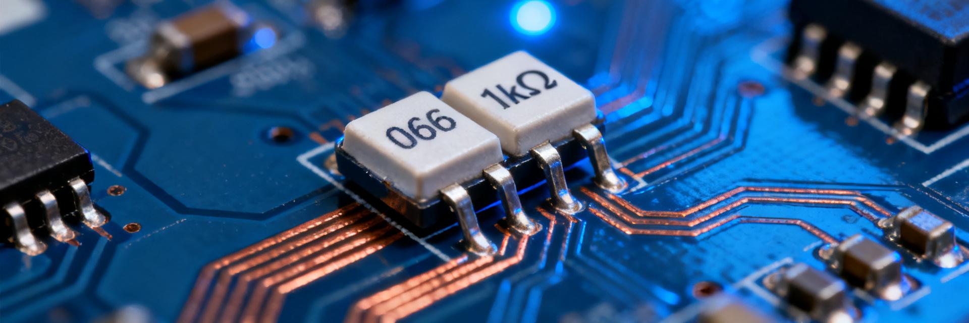
The Positioning of EXB-V4V102JV in the EXB Series
The EXB-V4V102JV belongs to the isolated chip resistor networks of Panasonic's EXB series. This series is renowned for its miniaturization and high integration, whereas the V4V sub-series is specifically designed for applications requiring independent resistor elements. Compared to other models in the same series, it offers two fully isolated resistors at a 1kΩ resistance value, making it suitable for circuit topologies that must avoid inter-channel interference.
0606 Package and Internal Circuit Topology
The device adopts a 0606 micro package (1.6mm × 1.6mm) and integrates two independent 1kΩ resistors internally. Each resistor element is routed through independent pads to achieve electrical isolation. This topology eliminates the risk of crosstalk caused by a common terminal, making it particularly suitable for signal conditioning and interface protection.
Impact of High-Density Mounting on PCB Layout
The footprint of the 0606 package is only about 30% of that of conventional discrete resistor solutions. In portable devices, this means you can pack more features into a limited space. However, note that high-density mounting places stricter requirements on pad design—it is recommended that pad spacing matches the device pins perfectly to avoid tombstoning or shifting.
Item-by-Item Breakdown of Core Specifications
Resistance and Tolerance: Practical Significance of 1kΩ ±5%
A ±5% tolerance means that at 25°C, the resistance range of each resistor element is between 950Ω and 1050Ω. For voltage divider circuits, this results in an output voltage deviation of approximately ±5%. If your ADC reference voltage requires higher precision, you will need to compensate for this error in software calibration. However, as a current-limiting or pull-up resistor, ±5% is typically more than sufficient.
Power and Voltage: Derating of 62.5mW and 50V
Each resistor element has a rated power of 62.5mW and a maximum working voltage of 50V. This means at 1kΩ resistance, the maximum allowable current is approximately 7.9mA. In actual designs, it is recommended to derate the power below 50% (i.e., 31.25mW) to enhance long-term reliability. For instance, in a 5V circuit, the current should be kept within 5.6mA.
Temperature Coefficient of Resistance (TCR) and Operating Temperature Range
The temperature coefficient of resistance (TCR) of the EXB-V4V102JV is ±200ppm/°C. Over the operating temperature range of -55°C to +125°C, the resistance variation with temperature is about ±2.5%. For precision voltage division, this requires additional calibration in environments with drastic temperature changes. However, for most consumer electronics operating within 0°C to 70°C, the thermal drift impact is negligible.
Structural Advantages of Isolated Resistor Networks
Unlike common-terminal resistor arrays, each resistor in the EXB-V4V102JV is completely independent. This eliminates coupling noise caused by common-terminal impedance, which is especially critical in differential signal paths or dual-channel sampling. Additionally, the isolated structure allows you to use the two resistors for completely different circuit nodes, offering higher flexibility.
Typical Application Scenarios and Circuit Design Points
Array Configuration in Voltage Divider and Current Limiting Circuits
In voltage divider circuits, you can connect two 1kΩ resistors in series to obtain a 2kΩ total resistance, or use them separately for two independent voltage dividing branches. In current-limiting applications, each resistor can independently protect an LED or an optocoupler. Note: Since the resistances are identical, the division ratio is fixed at 1:1. If other ratios are required, they must be paired with external resistors.
Applications in Signal Conditioning and Interface Protection
In I²C or UART interfaces, the EXB-V4V102JV can be used as a pull-up resistor. The two isolated resistors can independently pull up SDA and SCL, avoiding level interference caused by a shared pull-up. Furthermore, at the front end of analog sensor inputs, it can be paired with capacitors to form RC filters to suppress high-frequency noise.
High-Density Mounting Case Study in Portable Devices
Taking a smartwatch as an example, its motherboard area is typically less than 20mm × 30mm. Replacing two 0402 discrete resistors with the EXB-V4V102JV can save about 40% of the board area. Additionally, the 0606 package height is only 0.5mm, which helps reduce the overall device thickness. In actual layout, it is recommended to place the device close to the IC pins to shorten routing lengths.
Cost and Performance Comparison with Discrete Resistor Solutions
| Comparison Item | EXB-V4V102JV | Two 0402 Discrete Resistors |
|---|---|---|
| Footprint / Board Area | 1.6mm × 1.6mm | Approx. 2.0mm × 1.0mm (including spacing) |
| Mounting Cost | Single placement | Double placement |
| Channel Isolation | Excellent (independent elements) | Excellent (independent devices) |
| Resistance Matching | ±5% | ±1% available |
As shown in the table, the EXB-V4V102JV offers clear advantages in space and assembly efficiency, but if you require higher precision matching, discrete resistors still have an edge.
Alternative Selection and Common Design Issues
Replacement Logic for Different Resistance Values in the Same Series
The EXB-V4V series offers various resistance values from 10Ω to 1MΩ. If 1kΩ is not applicable, it can be directly replaced with other resistance models of the same package and power rating, such as the EXB-V4V472JV (4.7kΩ). When replacing, make sure to recalculate power and voltage derating to ensure they do not exceed the 62.5mW limit.
Precautions for Soldering and Reflow Process
The 0606 package is sensitive to the reflow soldering profile. It is recommended that the peak temperature does not exceed 260°C and the liquidus time is kept within 60 seconds. The recommended solder paste printing thickness is 0.1mm to 0.12mm; excessive thickness can easily cause tombstoning. If manual soldering is performed, the soldering iron tip temperature should be below 350°C, and the contact time should be less than 3 seconds.
Maximum Ratings Often Overlooked in Datasheets
In addition to power and voltage, the datasheet also specifies insulation resistance (≥1000MΩ) and dielectric withstanding voltage (100V). These parameters are critical in high-voltage isolation or high-impedance circuits. For example, in medical equipment, insulation resistance directly impacts patient safety and must not be ignored.
Key Highlights
- The EXB-V4V102JV integrates two isolated 1kΩ resistors in a 0606 package, featuring a ±5% tolerance and 62.5mW element power.
- The TCR of ±200ppm/°C and operating temperature range of -55°C to +125°C specified in the datasheet must be used in conjunction with derating.
- Typical applications include voltage division, current limiting, interface pull-ups, and RC filtering, particularly suitable for high-density mounting in portable devices.
- When selecting, attention must be paid to critical parameters such as power derating, soldering processes, and insulation resistance.
FAQ
Which parameters in the EXB-V4V102JV datasheet are most critical for voltage divider circuits?
Resistance tolerance, temperature coefficient of resistance (TCR), and power derating are core to voltage divider circuits. The ±5% tolerance determines the voltage division ratio error, ±200ppm/°C affects thermal drift, and the 62.5mW power limit requires you to calculate actual power consumption and apply derating.
How to select replacement models based on the specifications of EXB-V4V102JV?
First, verify that the resistance, package, and power rating match. If higher precision is required, choose a ±1% model; if higher power is needed, select a larger package. After replacement, always re-validate the derating conditions and soldering process.
How should EXB-V4V102JV be laid out in interface protection applications?
It is recommended to place the device close to the connector or IC pins to shorten routing. The two isolated resistors can be used for signal line and power line protection respectively. Meanwhile, ensure an intact ground plane to reduce noise coupling.
What is the impact of the insulation resistance specified in the datasheet on actual applications?
An insulation resistance of ≥1000MΩ means extremely low leakage current between channels, suitable for high-impedance sensors and medical devices. If insulation resistance degrades, it may cause signal crosstalk or measurement errors, requiring additional protection in humid environments.


