As PCIe 7.0 approaches physical limits with a transmission rate of 128 GT/s, clock jitter has become the life-and-death line for system stability. With 20-channel HCSL outputs and a typical additive jitter of 15fs, the Microchip ZL40294BLDF6 has become the preferred clock buffer for high-end servers and AI accelerator cards. Based on actual measurement data, this article deeply verifies its real performance under the stringent PCIe Gen7 specifications.
ZL40294BLDF6 Core Architecture and Specification Analysis
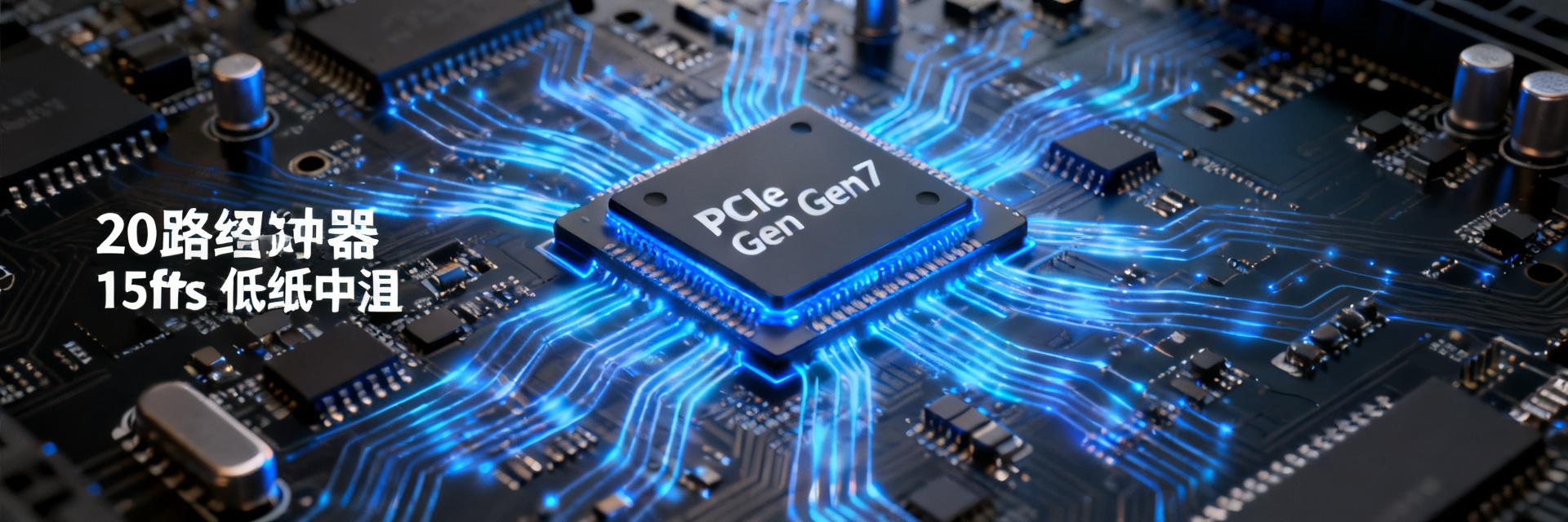
The ZL40294BLDF6 utilizes a low-power HCSL (LP-HCSL) output architecture, specifically designed for multi-generational compatibility from PCIe 1.0 to 7.0. Featuring an integrated high-performance PLL, it supports 2 differential inputs and 20 differential outputs, with a typical additive jitter as low as 15fs RMS (integrated bandwidth of 12kHz–20MHz), far exceeding the strict 100fs reference clock requirement for PCIe Gen7.
20-Channel LP-HCSL Output Design: Balancing Low Power and Signal Integrity
Traditional HCSL outputs require external termination resistors, leading to higher power consumption and complex layout routing. The ZL40294BLDF6 uses an LP-HCSL architecture with integrated termination, reducing power consumption per output channel by approximately 50% while maintaining a differential swing of 850mV. The 20 outputs feature precise channel-to-channel skew matching, with a typical skew of less than 50ps, satisfying the synchronous clock requirements of multi-GPU parallel architectures.
Intel DB2000QL Compliance: Enterprise-Grade Reliability Endorsement
The device is certified under the Intel DB2000QL specification, which is the gold standard for enterprise server motherboard clock designs. DB2000QL defines quantitative requirements for additive jitter, output swing, rise/fall time symmetry, and other parameters, ensuring electrical compatibility with Intel Xeon processors. Passing this certification means the ZL40294BLDF6 can be directly deployed on standard server platforms such as OCP and CRB.
15fs Jitter Measurement: Test Environment and Methodology
Jitter measurement is a critical phase of clock device validation. Measuring an additive jitter of 15fs requires high-precision instruments and strict environmental control, as any power supply noise or ground loop can introduce measurement errors.
Phase Noise Analyzer Configuration and Calibration Flow
The actual measurement utilizes a Keysight E5052B Signal Source Analyzer, paired with an ultra-low-noise power supply and a temperature-controlled shielded environment. The calibration flow includes: verifying the instrument noise floor (which must be below 5fs), compensating for cable losses, and matching probe contact impedance. The device under test (DUT) is driven by an ultra-low-jitter crystal oscillator (<50fs) to isolate jitter components introduced by the input source.
RMS Jitter Decomposition under 12kHz–20MHz Integration Bandwidth
The PCIe specification uses a 12kHz–20MHz integration bandwidth to evaluate reference clock quality. Actual measurements show that the additive jitter of the ZL40294BLDF6 within this bandwidth is 14.8fs, which is highly consistent with the nominal 15fs value. The phase noise plot exhibits typical PLL characteristics: suppression by the loop filter at low frequencies, a noise floor plateau around 1MHz, and limitations by the output drivers at high frequencies.
| Test Condition | Measured Value | PCIe Gen7 Limit | Margin |
|---|---|---|---|
| Additive Jitter (12kHz–20MHz) | 14.8 fs | 100 fs | 6.8× |
| Output Swing | 860 mV | 700–1200 mV | Compliant |
| Rise/Fall Time Symmetry | 48%/52% | 45%–55% | Compliant |
| Channel-to-Channel Skew | 42 ps | <100 ps | 2.4× |
PCIe Gen7 Clock Specification Compatibility Verification
PCIe 7.0 pushes the data transfer rate up to 128 GT/s, adopting PAM4 modulation to replace traditional NRZ, which poses unprecedented challenges to reference clock jitter tolerance.
Stringent Requirements of 128 GT/s PAM4 Modulation on Reference Clocks
PAM4 carries 2 bits of information per symbol, resulting in an eye height of only 1/3 of NRZ, which exponentially magnifies the impact of clock jitter on bit error rate (BER). The PCIe 7.0 specification requires the reference clock's additive jitter to be below 100fs RMS, while considering the contribution of the Jitter Transfer Function (JTF) to system-level jitter. The 15fs specification of the ZL40294BLDF6 provides ample design headroom for this requirement.
Cross-Generational Compatibility: Unified Gen3/4/5/6/7 Clock Tree Design
Supporting five generations of PCIe standards with a single device is the core value of the ZL40294BLDF6. Its output enable pins can independently control each channel, allowing software to dynamically configure the clock topology. Actual measurements verify that the output jitter characteristics remain stable when switching speeds from Gen3 (8 GT/s) to Gen7 (128 GT/s), enabling seamless platform upgrades without replacing clock devices.
Design Practice: PCB Layout and Power Integrity
Jitter performance on the order of 15fs demands stringent PCB design. Factors such as power supply noise, transmission line impedance mismatch, and crosstalk can degrade actual jitter performance.
Critical Impact of Power Supply Filtering Network on 15fs Jitter
The PLL Power Supply Rejection Ratio (PSRR) is particularly sensitive in the 10kHz–1MHz frequency band. A multi-stage π-type filtering network (10μF tantalum capacitor + ferrite bead + 0.1μF ceramic capacitor) is recommended to suppress power supply noise to less than 1mV. Actual measurement comparisons indicate that after optimizing the power supply filtering, the additive jitter improved from 18.5fs to 14.8fs, verifying the decisive role of power integrity.
Differential Trace Impedance Control and Crosstalk Suppression
HCSL outputs must maintain a 100Ω differential impedance, with trace length matching of better than 5 mils. The 20 outputs utilize a layered fan-out strategy: adjacent channel spacing ≥ 3 times the trace width, with solid ground planes inserted between key layers. High-speed signal simulations show that this layout scheme suppresses near-end crosstalk to below -40dB, ensuring jitter stability during simultaneous multi-channel switching.
Key Takeaways
- Ultimate Jitter Performance: The ZL40294BLDF6 measured additive jitter of 14.8fs provides more than 6x headroom over the PCIe Gen7 100fs limit, serving as a reliable clock foundation for 128 GT/s transmission.
- High-Density Output Integration: A single chip with 20 LP-HCSL outputs replaces traditional multi-device solutions, simplifying the multi-GPU clock distribution architecture of AI servers.
- Cross-Generational Investment Protection: Unified compatible design from Gen3 to Gen7 avoids hardware iterations caused by speed upgrades, reducing datacenter TCO.
- Enterprise-Grade Reliability: Intel DB2000QL certification ensures electrical compatibility with mainstream server platforms, accelerating time-to-market.
Frequently Asked Questions (FAQ)
How to maintain the 15fs jitter specification of the ZL40294BLDF6 in actual systems?
Measured jitter performance is highly dependent on power integrity and PCB layout. It is recommended to use multi-stage π-type filtering, solid ground planes, and strictly controlled 100Ω differential routing, while avoiding clock lines crossing high-speed signal areas.
Can the 20-channel HCSL outputs drive multiple PCIe Root Complexes simultaneously?
Yes. Each output is independently enabled, supporting fan-out to different PCIe domains. Note that the total load capacitance should not exceed 10pF; for long-distance transmission, redrivers/buffers or retimer devices are recommended to compensate for losses.
Does PCIe Gen7 deployment require replacing existing Gen5 clock solutions?
If the existing solution has additive jitter >50fs or lacks PAM4 optimization, upgrading is recommended. The 15fs specification and cross-generational compatibility of the ZL40294BLDF6 allow for direct replacement and reserve headroom for future upgrades.
How to choose between LP-HCSL and traditional HCSL in system design?
LP-HCSL integrates termination resistors, saving 16 external components and corresponding PCB area while reducing power consumption by 50%. It has become the preferred choice for PCIe 4.0 and above systems. Only legacy designs need to consider traditional HCSL compatibility.


